Brief Description
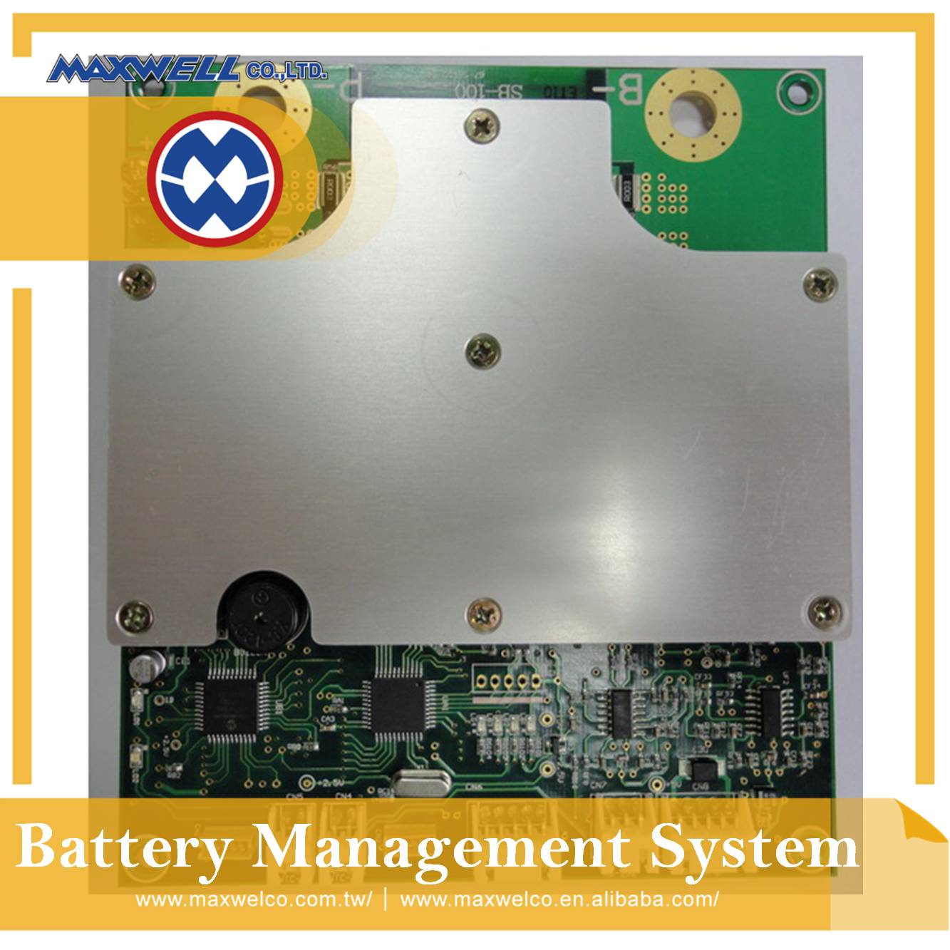
SB100-12-60
4S/ 60A LiFePO4 Car Starter Battery BMS
Features
1. Rated continuous discharge current: 60A
2. Gradient Current Management (GCM): Discharge current higher than 60A will launch this function, allowing
discharge current to flow per differential current draws, giving distinct working time spans.
3. Max discharge current: Peak current 900A. with delay time for 10Ms.
4. Floating Battery Balance by Current Bleeder: Intelligent cell balance starts when the cell volts go over 3.50V,
but it acts only on the cells that have volt variance, higher by 40mV than the lowest one,
designed to bleed current of cells by from 40mA to 300mA,
5. Mosfet Management: Current parallel snubber designed for a purpose to keeping Mosfets safe from surges.
6. Auto Shunt Down Mode with no current consumption: It shuts down the system, showing 0 volt measured at
terminals of battery, under two conditions as follows: (1).When a status of no load lasts for 24 hours on BMS, and
(2).when it is in UVP status.
7. Low Voltage Start Energy Reserve Mode(LVSER Mode): When a cell volt drops down to 2.90V, LVSER
function acts to break tickling current drains. It intends to break current outflow not involved with driving or igniting
operations. The LVSER Mode is an Energy-save mode to maintain margin capacity for a car to start up again at its
low energy storage state, ranging from 2.90V to 2.4V of a cell, while there is on-going current draw in the car, until UVP
volt of 2.40V shows up.
8. LVSER Disabled: LVSER function will self-disable once car alternator fails to supply power to battery.
During this moment, the LVSER Disabled can assure the battery to enjoy reserve capacity or originally stored energy
(RC value, Reserve Capacity Value) .
9. BEMF protection: The BMS has protection for itself against the back electromotive forces or AC ripples from the car
alternator.
10. Double core design guards the BMS against interference in operations
|
Ignition stage |
Driving State |
|||
|
Policy for high current draw protection & electric loop safety |
Policy for automotive power system safety detection |
|||
|
Keeping safe by snubbers for Mosfet switch and by fly wheel diode from back EMF on the system |
Current sensor circuit with current sharing design sampling current flow to keep back rise in temperature |
Battery energy returns to the system from LVSRE once when alternator fails |
||
|
Energy Saving & Energy Reserve Policy |
Policy for Cell Safety and battery energy operability |
|||
|
Low voltage start reserve energy (LVSRE) |
No power dissipating when without a load on after 120Hrs |
Battery Communication |
Discharge current management |
Smart battery balance |
Intelligent double core system guarding the BMS against noise and car AC ripples
Key Specification and Electrical Characteristics, based on 4S battery
|
Item |
Condition |
Unit |
Typical |
||
|
Standard Charge |
Charge Voltage; CC/CV 14.4 |
V |
14.4 |
||
|
Over Charge Current Protect (OCCP) |
Max charge current |
A |
100 |
||
|
Over Charge Current Protection(OCCP) detect time |
S |
5 |
|||
|
OCCP Release detect time |
mS |
200 |
|||
|
Over-load Discharge Current Protect |
Cell Voltage Range |
V |
2.4 ~ 3.85 |
||
|
Load Short Circuit Current Protect > |
A |
900 |
|||
|
Load Short Circuit Current Protect Delay Time |
mS |
10 |
|||
|
Operation time for Over-load Discharge Current Protect per Max Discharge Current, Iout=, , with +-10%, @25 ℃, |
0.15 S |
A |
900 |
||
|
0.3 0S |
A |
800 |
|||
|
0.70 S |
A |
500 |
|||
|
1.50S |
A |
350 |
|||
|
3.00S |
A |
150 |
|||
|
7.00S |
A |
100 |
|||
|
15.00S |
A |
80 |
|||
|
Rated Continuous Discharge Current |
A |
60 |
|||
|
Over Charge Volt Protect (OVP) |
OVP (Cell Vmax) |
V |
3.85 |
||
|
OVP Release Voltage ( Cell Vmax ) |
V |
3.45 |
|||
|
OVP Delay Time |
Sec |
0.2 |
|||
|
Low Voltage Start Energy Reserve (LVSER) Volt |
For Non-Drive or Non-Start-up Current Drain Protection(8<A) |
LVSER Mode Cutoff Voltage (Cell Vmin),@ |
V |
2.90 |
|
|
LVSER mode parameter |
Condition of current draw to trip LVSER Mode < |
A |
8+/-1 |
||
|
Wakeup-and-Sleep Self-recognition |
|
YES |
|||
|
Working current consumption at wake-up state |
mA |
12 |
|||
|
Voltage Range for Energy-save Mode 2.90V~2.4V( Reserved for Re-start up) |
V |
2.4~2.90 |
|||
|
Current Drain in LVSER mode < |
uA |
10 |
|||
|
Working every 5S when with a load, and then sleep |
S |
15 |
|||
|
Alternator Failure Mode |
LVSER mode self-disabled as alternator fails. (Software-controlled self-recognition) > |
|
YES |
||
|
No-load Shut-down |
Shut down with no load after count down (Default) |
H |
120 |
||
|
No load Shut-down Current Drain |
u A |
1 |
|||
|
Trigger-up Current to shunt down mode |
Current signal to Trigger up when in shunt mode> |
mA |
10 |
||
|
Trigger-up Time in shunt down mode |
mS |
200 |
|||
|
Under Voltage Protect (UVP) |
UVP Cutoff Voltage (Cell Vmin) @ |
V |
2.40 |
||
|
UVP Shut-down Current Drain ( Cell Vmin2.4V) |
u A |
2 |
|||
|
UVP Release Voltage ( Cell Vmin) |
V |
2.80 |
|||
|
UVP Delay Time |
Sec |
3 |
|||
|
Battery Balance |
Balance Start Volt, VH-VL= 40mV, and V= |
V |
3.50 |
||
|
Balanced Volt @Vmax=3.5V or VH-VL= |
mV |
15 |
|||
|
Float Balance Capability (3.5V/22R)*25%~100% |
m A |
40~ 300 |
|||
|
Self-adjusting Balance Current Bleeder |
|
YES |
|||
|
LED indicator for balance signals |
|
YES |
|||
|
Mosfet Switch Management |
MOSFET switch with current serial snubber design |
|
YES |
||
|
Over- Temperature Protect(OTP) |
Charge OTP Detect as TEMP out of between |
℃ |
0~70 |
||
|
Charge OTP Release as temp. returns inside |
℃ |
5~60 |
|||
|
Discharge OTP Detect as TEMP out of between |
℃ |
-30~75 |
|||
|
Discharge OTP Release as TEMP returns between |
℃ |
-20~65 |
|||
|
BEMF Voltage Protect |
designed against BEMF and car AC ripples |
|
Yes |
||
|
Temperature |
Ambient temperature for BMS |
℃ |
-30~80 |
||
|
RH% |
|
% |
5~90 |
||
|
Dimension |
LWH 150mmx130mmx18mm |
|
|
||